Cascade Dafo offers a guide for the quality and capture of digital scans, covering scanning methods, quality control of files, and submission guides and requirements.
Rather than shipping a cast to us, practitioners have the option to scan and upload the file via DAFO e-Orders, avoiding inbound shipping costs and benefiting from additional order tracking through production and shipping cycles.
For full scanning details, be sure to utilize this guide and its quick links available to the right to jump between sections.
| Want to watch videos of how to scan the outside of a cast? Go to our YouTube Playlist. |
Here are a couple quick tips:
Scanning MethodsWhen sending your scans, please tell us which scanning method you used: Scan the outside of the cast: Scan the plaster positive mold Direct scan of patient: |
Accepted File Formats.stl (recommended) File sizes between 1MB and 25MB. Try to keep your scan file to a reasonable size to ensure smooth transmission (apx. 10MB). |
Overview
For more than a decade, Cascade Dafo has been utilizing a digital manufacturing process that results in an exceptionally accurate brace fit. This approach streamlines the ordering process, allowing practitioners to send digital scans rather than shipping casts to Cascade Dafo. We will continue to update our digital scanning guidelines and recommendations as scanning becomes a more common practice in the O&P industry and as the technology advances.
Benefits of Digital Scanning
|
Potential Physical Models
|
Accepted File FormatPlease convert your file to one of these types before sending.
File sizes between 1-25MB. Save the scan file in millimeters to ensure it imports to proper scale. |
Scanning ResourcesFor detailed techniques, take our free ABC-approved online course — Casting and Scanning for DAFOs — on the Cascade Dafo Institute. For how-to videos, visit our YouTube Playlist on Scanning the outside of the cast. |
Scanning Equipment
|
How to send us your filesEnter the order details directly into our e-Orders system and upload your digital scan files to: orders.cascade.com You can add photos or videos, too! |
SupportIf you have any questions, contact: |
||
Tips for Scanning
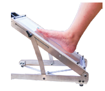
Secure the fiberglass cast or plaster positive to a fixed location (if scanning a patient, ensure they can hold still). Position the physical model to capture all planes with the toes pointed up to expose the dorsum of the foot. We recommend scanning the outside of the cast to accurately capture the desired position of function while minimizing the prep work necessary to send an order to Cascade Dafo.
Tips for Scanning Each Model Type
|
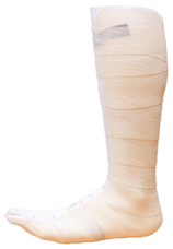
Outside of fiberglass cast:
|
 |
|
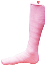
Plaster positive mold:
|
 |
|
Direct scan of patient:
|
 |
Scanning and Software
We have tested a number of scanners and software combinations and found that the volume of the scan can vary from the physical model. In general, we have noticed that the higher-end scanners have greater accuracy. Factors to consider before selecting a scanner and software combination include: number of patients, practitioners, technicians, workspace, etc.
Examples of Scanning Setups
|
Phone:
|
Handheld:
|
||
|
Advantages:
|
Disadvantages:
|
Advantages:
|
Disadvantages:
|
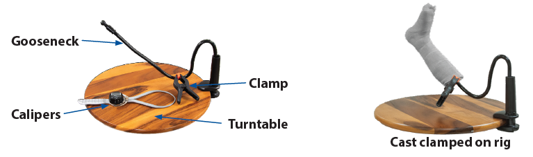
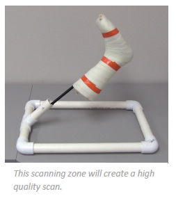
Rig for scanning outside of fiberglass cast:
- Calipers: to measure cast thickness
- Gooseneck phone holder: allows adjustable angle for scanning casts.
- Turntable: allows ease of cast rotation to capture all planes.
- Clamp: to secure cast to gooseneck to avoid unwanted movement.
Common Scanners Used in O & P
- Comb App
- Techmed 3D BodyScan
- Handheld
- https://techmed3d.com/hardware/
- Revopoint POP 4
Suggested Software
- Meshmixer
- Open source allows you to crop, fuse, and evaluate scan of your physical model
- https://www.meshmixer.com/
- Blender
- Open source with steep learning curve
- https://www.blender.org/
- Canfit
- License required
- https://qwadra.com/solution/canfit-design-software/
Accuracy Review
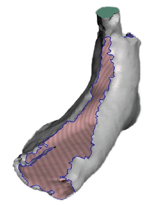
A difference in measurements between scan and physical model affects the volume and intended fit of the DAFO. All scanners have the potential to create a scan that can pass a visual identification check, yet still have a dimensional difference greater than +/-2mm. The only way to identify this issue is to measure scan dimensions against the physical model. We recommend measuring at three points or at minimum the m/l metheads.
|
Tips to resolve:
|
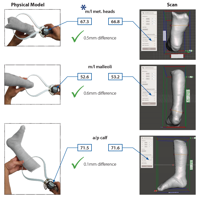
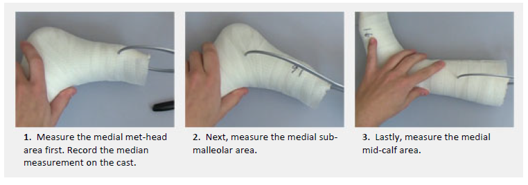
![]() The minimal measurement recommended for determining accuracy.
The minimal measurement recommended for determining accuracy.
Scan Evaluation
We have identified anomalies which can occur during the scanning process that may not affect our ability to fabricate a well-fitting DAFO. There are times when the anomaly is too great and requires a rescan of the physical model. The following are examples of what we are able to correct, not able to correct, and tips to resolve.
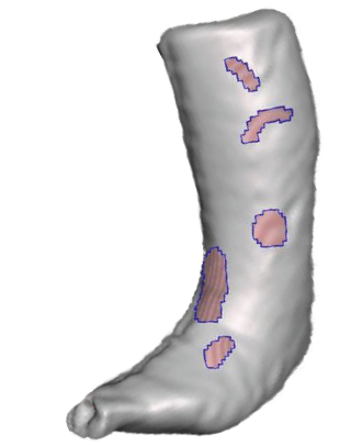
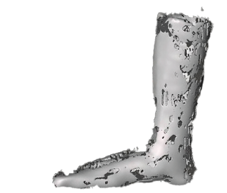
| Holes: Pockets of missing data in the scan from the physical model. | |
|
Able to correct:
|
Unable to correct:
|
|
Tips to resolve:
|
|
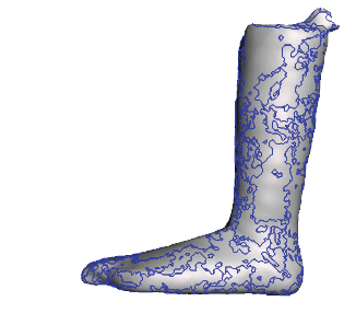
| Untrimmed: Scan has extra data not related to the physical model. | |
|
Able to correct:
|
Unable to correct:
|
|
Tips to resolve:
|
|
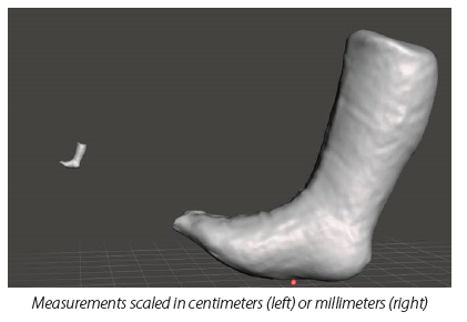
| Scale Issue: The exported dimensions are saved as an increment other than millimeters (mm) which results in the scan being sized differently than the physical model. | |
|
Able to correct:
|
Unable to correct:
|
|
Tips to resolve:
|
|
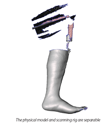
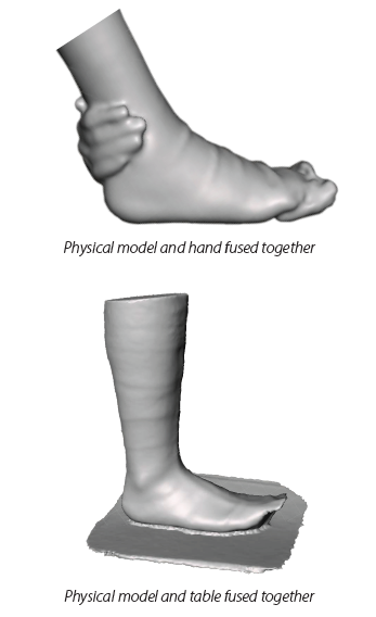
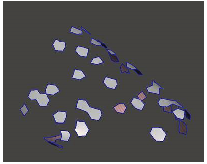
| Unfused: The independent shapes are not combined into a single digital object. | |
|
Able to correct:
|
Unable to correct:
|
|
Tips to resolve:
|
|
| Drifted: During the scanning process, aspects of the physical model shifted in one or more planes affecting the anatomical features. | |
|
Why unable to correct:
|
|
|
Tips to resolve:
|
| File Corruption: Scanning | |
|
Why unable to correct:
|
|
|
Tips to resolve:
|
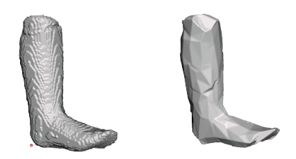
| Low Resolution: Scan shape with large polygons distorting the details of the physical model. | |
|
Why unable to correct:
|
|
|
Tips to resolve:
|
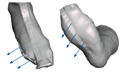
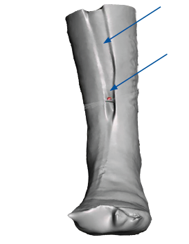
| Unclosed Seam: Physical model was scanned with the cut seam open. | |
|
Why unable to correct:
|
|
|
Tips to resolve:
|
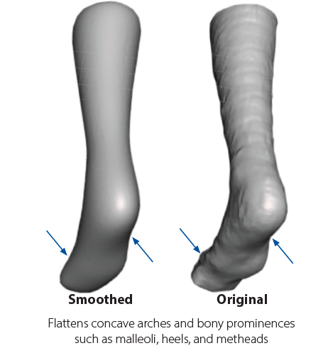
| Over-Smoothed: The loss of anatomical features during a smoothing process. | |
|
Why unable to correct:
|
|
|
Tips to resolve:
|
How to Scan Outside of Casts to Order DAFOs
| Want to watch videos of this process? Go to our YouTube Playlist. |
1. Cast accuratelyUse a thin, even, white fiberglass wrap to cast the foot and lower leg in the patient's best position of function. Capture angles as close to the balanced position — vertical heel, level forefoot, and 3 degrees of dorsiflexion — as your patient can use in the finished brace. |
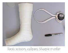
2. Collect cast thickness informationPrepare
|
 |
|
Measure
Record
|
|
 |
|
3. Scan the outside of the cast
|
 |
4. Check raw scan and resolve issues
|
5. Export scan
|
6. Final check of exported scan
|
7. Order and upload your scan
|
If you need assistance, contact us at:
Cascade Dafo Customer Support
CustomerSupport@dafo.com
800.848.7332 | intl: +1 360 543 9306 | fax: 877.856.2160